Single 5/8 Flower Pot Antenna
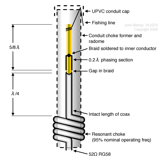
The Single 5/8 version of the Flower Pot simply substitutes a 5/8 wave-length section for the top quarter wave of the basic half wave antenna design. The arrangement is shown in the sketch below. The 5/8λ radiator uses a 0.2λ (shorted) co-ax phasing stub to resonate the 5/8λ element. In a conventional 5/8λ mobile whip, an inductor is used to bring the 5/8λ element to resonance; however, in this Flower Pot style of antenna, using a co-ax phasing (or delay) stub suits the construction technique and has the advantage of being able to be precisely determined and cut at the construction stage.
The antenna configuration is similar to, but slightly shorter than, the “Gain Sleeve” antenna described in the RSGB Hand-book (6th Edition – figure 13.99, which itself is derived from the reactance – or shunt – fed 5/8λ monopole antenna at figure 13.84 of the handbook).
The Gain Sleeve antenna achieves an effective radiating element length of one wavelength and, since the aperture is twice that of a half wave dipole, a theoretical gain of 3dBd (gain over a dipole) could be achieved.
However, note that the Handbook indicates that in practice, the Gain Sleeve antenna would realise about 2.5dBd. The effective radiating element length of the Single 5/8 Flower Pot is 7/8λ suggesting it would have somewhat less than 2.5dBd gain.
2m Construction

2m Single 5/8 Flower Pot
Construction of the Single 5/8, whilst a little more involved than the basic half-wave antenna, is again fairly simple.
From the top of the co-ax, measure off an approximate 5/8λ distance to locate the position of the feed point. Make this distance slightly longer than the exact 5/8 length (say 10mm) as you will trim the top element to length later.
At the feed point, cut away the outer sheath and braid so as to form a 2-3mm gap.
From the edge of the gap, measure off the distance for the 0.2λ section. For solid polyethylene dielectric cable, this is 276mm for 2m and 755mm for 6m. From this point, expose sufficient braid to be able to make several pigtails to be soldered to the inner conductor and then the braid and outer sheath for the remainder of the top element length can be stripped off. At the 0.2λ point, cut into the inner dielectric to expose about 3mm of the inner conductor and solder the braid pigtails to the inner conductor.
Trim the top element to length. It will be most unlikely that you have to further trim the antenna later but you could leave a small, extra margin to allow some later adjustment if desired; however, builders of this antenna have reported that further trimming was unnecessary so you should have confidence in cutting the element to length at this stage.
To complete construction, follow the same procedure as for the half-wave antenna. As in the half wave version, use a length of nylon fishing line to pull the radiator taut and clamp it in place with the conduit cap. The length of the conduit above the choke can be 10 to 20mm longer than the total length of the quarter wave and 5/8 wave elements.
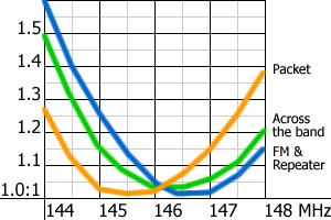
The Single 5/8 has a slightly sharper VSWR response than the basic half wave Flower Pot and, although a VSWR of less than 1.5:1 across the 2m band can be achieved, the antenna can be cut to favour the high FM portion of the band or the lower packet portion. The dimensions derived during my experiments for 2m are given in the following table; these dimensions have since been validated in further builds of the antenna.
| Desired Portion of Band | Upper 5/8 element | Bottom “λ/4” | Choke Coil |
|---|---|---|---|
| Across the Band | 1228mm | 465mm | 9 turns on 25mm former |
| FM & Repeaters | 1224mm | 465mm | |
| Packet low band | 1236mm | 480mm |
The VSWR curves for the three antennae are shown in the next figure. Note that the “Across the Band” curve purposely favours the higher end of the 2m band.

VSWR curves for three antennae. Note that the "Across the Band" curve purposely favours the higher end of the 2m band.
6m Single 5/8 Version (and using the Antenna at Other Frequencies)
The physical/mechanical properties of conduit are not conducive to building a 6m or a lower frequency version of the single 5/8 antenna because conduit is not sufficiently rigid to maintain straightness and it retains a set after a hot day.
I have, however, built a 6m single 5/8 by terminating the top end of the phasing stub onto a standard mobile base mounted on a conduit cap and using a plain (braided) mobile whip for the remainder of the top 5/8 element. This way the conduit length is approximately halved and is less susceptible to bending. If you want to try building one doing this, the length of the whip will, depending on its diameter, probably be marginally longer than the equivalent length if it was made using the co-ax inner. Also when using a whip, the overall length of the 5/8 element will need to include the length of the phasing section. Otherwise, the dimensions readily scale from the 2m antenna.
The antenna can be scaled to any operating frequency using the choke data given previously. Note that the 2m single 5/8 is close on 2m long; 25mm conduit is mechanically OK for this length and this suggests that the ideal application of this style of antenna is for frequencies around 2m, ie boating, aircraft and the VHF two-way communications bands.
When working out the phasing stub length for other frequencies, don’t forget to take the velocity factor of the cable into consideration.